Labor-constrained tending
Template Preview — Fictional automation provider. Systems, results, credentials and contact details are illustrative; no inquiry is transmitted.
ROBOTICS · VISION · CONTROLS · DATAConnect the line.
Connect the line.
Clarify the outcome.
Map the physical process, control states and production-data boundary before committing to equipment.
INTERACTIVE LINE MAP / DEMOSelect a system node
03 / ROBOTHandling + state
Coordinate reach, payload, tooling and safe recovery around the process.
Illustrative architecture — confirm every interface during discovery.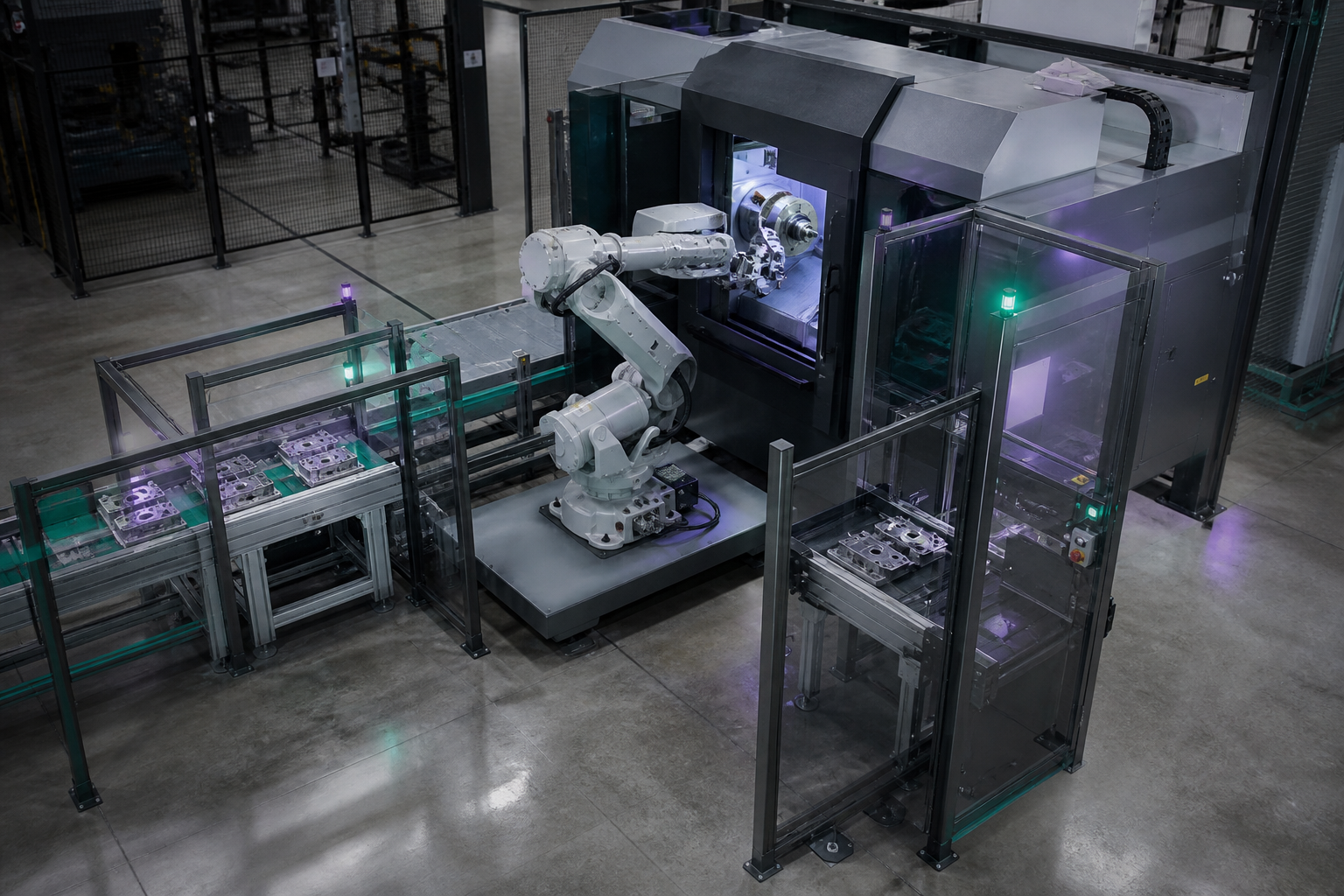 CONNECTED CELL / ILLUSTRATIVE
5system states mapped
Inline inspection
Mixed-model assembly
Architecture before equipment.
Each system concept exposes the process, control and data decisions that have to align.
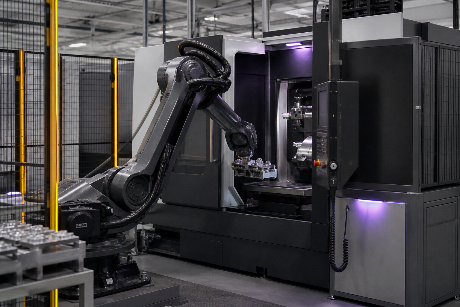
01 / R1 CELL CONCEPT
KINETRA TEND / R1
A fictional guarded machine-tending cell concept connecting workpiece presentation, robot handling and machine-cycle signals.
- Machine interface
- Demo OPC UA + discrete I/O
- Payload envelope
- Illustrative 12 kg
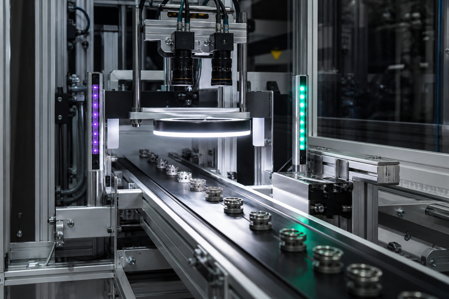
02 / Q2 INSPECTION CONCEPT
KINETRA VISION / Q2
A fictional inline vision concept connecting controlled imaging, decision rules, rejection and record context.
- Inspection rate
- Illustrative 45 parts/min
- Camera topology
- Demo dual-view station
03 / A3 ASSEMBLY CONCEPT
KINETRA FLEX / A3
A fictional mixed-model assembly cell concept with recipe control, guided verification and structured station handoffs.
- Station count
- Illustrative 3 modules
- Recipe model
- Demo variant routing
INTEGRATION STACK / 02One outcome.
One outcome.
Four connected layers.
An automation proposal becomes credible when responsibility is explicit from the physical process through production context.
See integration capabilityProduction context
MES orders, identifiers and approved reporting boundaries.
Line coordination
Routing, buffering, recipe state and line-level exceptions.
Cell control
PLC sequence, safety state, robot tasks and inspection decisions.
Physical process
Parts, tooling, sensors, guarding and machine interfaces.
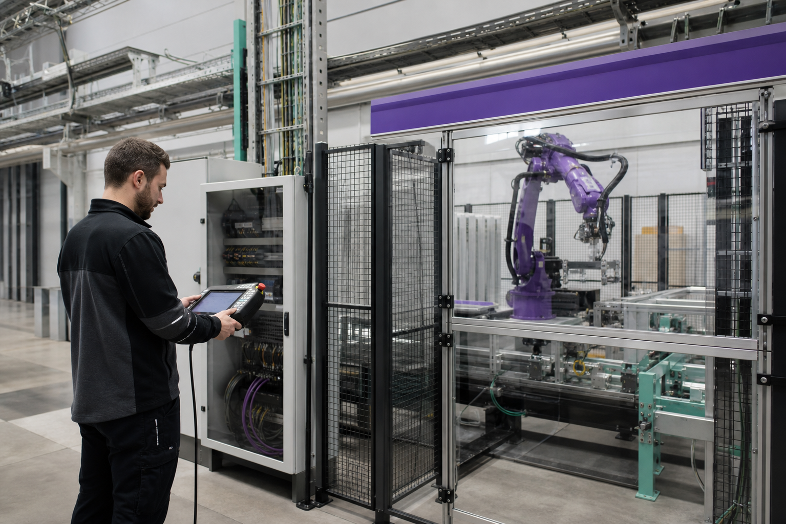
ACCEPTANCE PATH / 03
Make handoff part of the design.
Discovery, controls review, FAT, site acceptance and lifecycle support appear as one visible sequence—not hidden after the proposal.
- 01Constraint & acceptance criteria
- 02Interface & safety review
- 03FAT → SAT → controlled change